“Everything you imagine is real,” is a well-known, inspirational quote by Pablo Picasso often interpreted in the context of the power of the imagination. This phrase parallels something I find true in flex and rigid-flex design. Often, the applications for flexible circuits are simply limited by our imagination. One of the favorite parts of my job are the days when I meet with a group of engineers and designers to talk about flex and rigid-flex. We might do a “lunch and learn” with a general overview of the technology or address a specific challenge. It is always helpful to bring samples to pass around and show different features. Usually, looking at a sample will spark an idea and the comment, “I wonder if we could do something like this.” From there, the brainstorming begins.
Knowing this month’s theme was going to be “everything starts with design” made me wonder if I could make something similar happen by looking at pictures rather than holding flex and rigid-flex in your hands. If these pictures help generate an idea for a new design, I would love to hear about it. If not, I will point out some of the best practices being utilized in these designs that should be beneficial to those new to flex and design—and maybe a good reminder to those more experienced. Let’s start with a basic flex design.
Figure 1 is a straightforward, single-sided design connecting two components. I imagine this could replace wire and save space and weight. It could also replace a rigid board and solve a packaging issue. The FR-4 stiffeners are important here to support the weight of a heavier component and prevent damage to the flex circuit.

Figure 2 is a double-sided flex, using a combination of through-hole and SMT components. In this image, you can see the polyimide stiffener in the tail area. Zero insertion force) (ZIF) connectors are a common termination method for flex and require tight tolerances for both the outline and the overall thickness. Polyimide stiffeners are commonly used to increase the thickness to meet this specification.
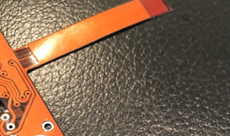
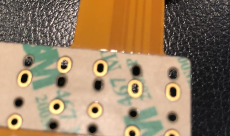
Figure 3 is another example of a double-sided flexible circuit. You can see from the photo that this design also uses a polyimide stiffener. In this case, the stiffener is functioning as a support for that component area, adding a bit of thickness. The other interesting thing to note about this sample is the use of pressure sensitive adhesive (PSA). This is something that doesn’t really make its way into design guideline discussions but is commonly used to mount the flex inside of the unit either to be sure it remains in place through the life of the product or to help anchor a section that is going to have a lot of flexing in end use. This is one of those items that calls for imagination.
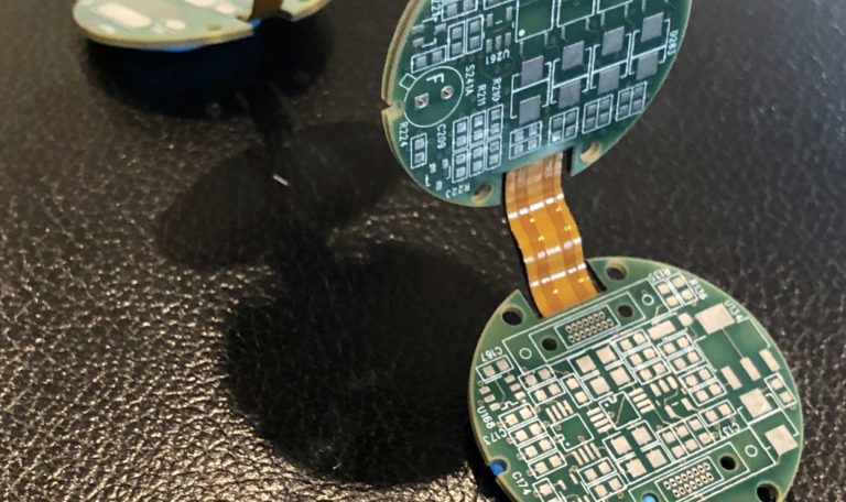
Figures 4 and 5 are images of a double-sided flex that does an excellent job of taking advantages of packaging benefits of a flexible circuit. The shape of a flex interconnect truly allows for creativity and imagination. In Figure 4, you can imagine how this will simply drop into the unit, eliminating wire and assembly. In Figure 5, you can also imagine how that tail breaks off from the main flex area. What you can’t see is the PSA being used to guide and secure that during installation.

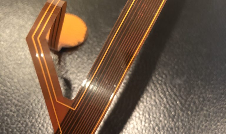
Figure 6 shows an example of a simple rigidflex. In this case, the FR-4 stiffeners have plat ed through-holes both mechanically supporting and electrically connecting with the flex layers. This particular design required heavier copper for shielding and was in danger of not being flexible enough for the end application. To solve that problem, a loose-leaf construction was used. In this case, the layers were split into two sections.
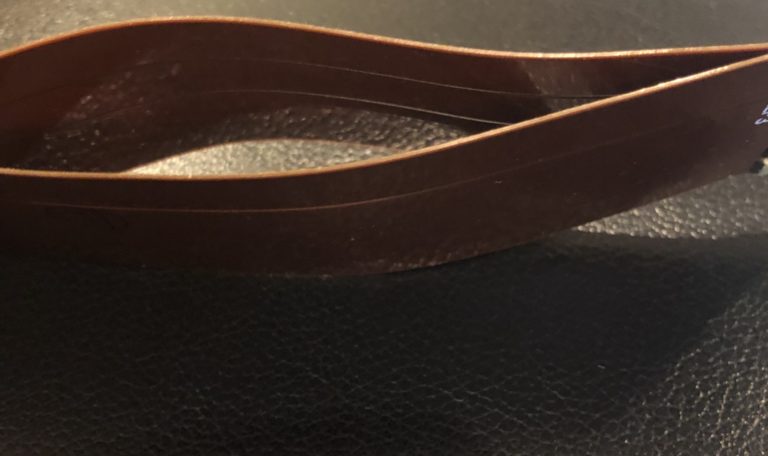
Figure 7 is also a rigid-flex design, having circuitry included in the rigid areas. This sample gives one of my favorite views of the power of loose-leaf construction. This design did not have heavy copper but did have 10 flexible layers that if all bonded together, would never allow for the flexibility required in end use. Something that isn’t shown well in the photo is the use of crosshatch shielding in the flexible layers, which is also added to the flexibility of each of these layers.
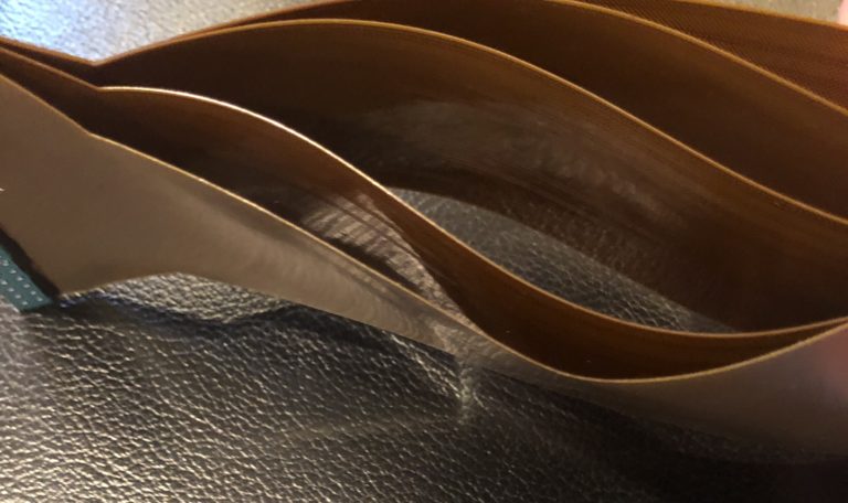
Figure 8 displays a common rigid-flex construction with two rigid areas connected by flexible layers. I wanted to include this for two reasons. First, it’s simplicity. This type of design is one that many start with when they first move into rigid-flex. The concept is simple, and this is one of the lowest cost forms of rigid-flex design. The second thing I wanted to point out with this image is the use of strain relief with a simple bead of epoxy where the flex and rigid layers meet. This prevents damage to the flex in that critical area.

Figure 9 is another example of a rigid-flex construction and demonstrates how the flexible tail areas aid in packaging. This is becoming more and more important as we are challenged to fit more sophisticated electronics into smaller and smaller spaces. This sample also shows the crosshatch copper pattern in the bend areas to improve the flexibility of the design.
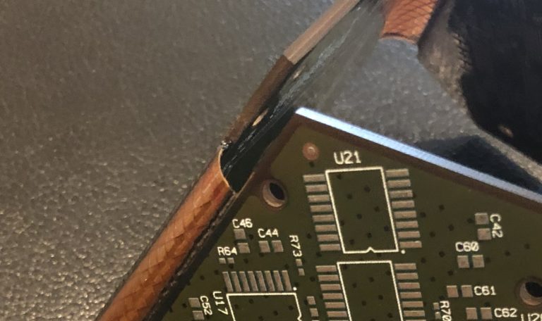
Figure 10 is also a rigid-flex design, which is a little more complex with various tails splitting off from the main flex area. This is an excellent use of imagination and fits well with rigid-flex capabilities. Again, you can again see the crosshatch copper pattern to improve flexibility in the photo. What you cannot see in is the strain relief added to each section area that has a flex tail or the fact that this design will ultimately be packaged with four different bending and folding areas and the tail being routed in all directions.
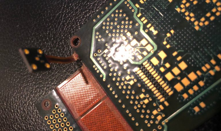
Figure 11 is one final rigid-flex design that also shows the power of flex and the potential for packaging solutions. You could imagine this rigid-flex moving up and over a fixed piece in the unit while connecting complex electronics. This is an excellent use of rigid-flex to solve a packaging issue.
Flex and rigid-flex design is one of those things that allows engineers and designers to be both creative and science-driven at the same time. Hopefully, seeing some of these samples will help spark some new and creative options for solutions that need flex and rigid-flex to solve their space, weight, and packaging constraints.